by Shawn Walters
Stereolithography (SLA) is a process invented by Chuck Hull in which he was granted a U.S. patent (US4575330) in 1986 and started 3D Systems, Inc. In 2021, 3D Systems made the divestment decision to discontinue the printing of parts and sold off the “On Demand” division to what is now Quickparts Acquisition Inc., doing business as “Quickparts”.
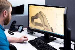
Quickparts SLA is an additive process which begins with a customer sending in a form of computer-aided design (CAD) file of a desired part to be built. The Quickparts setup team then converts the CAD file to a .stl file for processing with our setup software. The software will slice the file into 0.004”(0.102mm) layers for standard resolution and 0.002”(0.051mm) layers for high resolution. The software will also generate supports which are thin grided walls which will be built from the platform to the bottom of the part to allow removal from the platform without damage to the part. The software will also detect any thin or faceted (i.e. appearance of a stop sign instead of smooth circle/surface). Once the file is properly checked, sliced, and supported, it will be sent to the appropriate 3D printer loaded with the desired material and size appropriate for the dimensions of the part to be built. 3D printers consist of a large tub or tank, called a vat, to hold the liquid form of the material to be used, a build platform which is raised and lowered from the top to the bottom of the vat, a recoater, which is an arm which travels back and forth across the top of the vat spreading a new layer of material as each layer is printed, and finally a UV laser with optics and mirrors which focus and direct the beam from the top of the machine down to the vat of material.
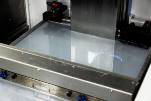
When a job is started on a machine, the build platform lowers down into the liquid material, called photopolymer, and the recoater sweeps material across the platform the thickness of one layer dependent on the desired resolution (Normal/High Resolution). The printer will use the laser to project and draw the first layer of supports. When the laser UV light draws in the material, it solidifies the material. When one layer is complete, the platform will drop down farther into the material the thickness of the next layer and keeps repeating these steps until the supports are complete and all the layers of the part according to the provided .stl file.
SLA parts can be built in various materials at Quickparts as follows:
| Standard Resolution: | High Resolution: |
| Accura 25 | Accura 25 |
| Accura Xtreme Grey | Accura Xtreme Grey |
| Accura Clearvue | Accura Clearvue |
| Accura 60 | Accura 60 |
| Accura SL 7820 Black | Accura SL 7820 Black |
| Accura Xtreme White 200 | Accura Xtreme White 200 |
| Accura Bluestone | |
| Accura 48 |
High resolution parts are much better quality parts and able to print small features and text better, but will take more time to build because the layers are sliced half as thin as the standard resolution causing the machine to have to print double the number of layers.
Platform sizes go up to the following :
Normal/Standard Res: 59″ × 29.5″ × 21.5″ (1500 mm × 750 mm × 550 mm)
High Res: 15″ × 15″ × 10″ (380 mm × 380 mm ×254 mm)
Standard SLA Tolerance for parts produced are as follows:
X & Y Coordinates – ± .005”(.127mm) for the first inch(25.4mm)
± .002”(.051mm) for each additional inch
Z Height – ± .010”(.254mm) for the first inch
± .002”(.051mm) for each additional inch
Minimum feature sizes are as follows:
Standard Resolution – 0.025″ (.635mm)
High Resolution – 0.010″ (.254mm)
Minimum Wall Thickness’ are as follows:
Standard Resolution – 0.025″ (.635mm)
High Resolution – 0.015″ (.381mm)
Minimum Hole Sizes are as follows:
Standard Resolution – 0.030″ (.762mm)
High Resolution – 0.030″ (.762mm)
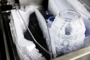
When the job is complete, the platform with the part and supports is raised out of the material and allowed to drain until able to move to a transport cart and sent to the cleaning department. In the cleaning department, depending on the material used, the part goes through a series of progressive steps being rinsed with various cleaning solvents. Then the part is separated from the supports by hand tools, such as scrapers and blades and removed from the platform for the final rinsing process making sure all resin is removed from any tubes and channels. Once properly cleaned, the part is moved to a UV post cure oven to dry and final cure the part.
Once cured, parts are moved to the finishing department.
7 Finish levels are offered in SLA as follows:
Natural Finish – Remove supports, wash, and post cure. (No sanding performed)
Standard Finish – Remove supports, wash, post cure, sand areas where supports were attached with 320 grit sandpaper, sandblast with 320 grit aluminum oxide sand. Note: ABS Black parts may receive an additional coating
Paint Ready Finish – Standard Finish plus remove all build/layer lines on the visual (cosmetic) surfaces with 320 grit sandpaper, sandblast with 320 grit aluminum oxide sand, apply primer to all surfaces and sand with 600 grit sandpaper (build/layer lines will be visible on non-cosmetic surfaces
Painted Finish – Paint ready finish with customer specified paint color applied
QuickClear – Standard finish with clear coat applied
Clear Part Finish – Remove all build/layer lines from all surfaces with 400 grit sandpaper and apply clear coat
Custom Finish – Specified by the customer
Other secondary post process offered in the finishing process such as: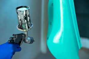
- Custom Paint
- Decals
- Inserts
- Secondary Machining
- Minor Assembly
Orders move to the inspection area once finishing is complete for the following standard inspection:
Visually inspect the part by rotating it in all directions under favorable light conditions. Inspect for supports, they should not be left in any holes or slots. No layer/build shift. No broken features or chips. No delams. Should be painted per Work Order and free of cosmetic defects and/or drips or runs. Dimensional check X, Y, Z of 1pc of each geometry to standard SLA tolerances unless specified differently on the Work Order.
Upon request more detailed inspection such as First Article Inspection (FAI) can be performed using the appropriate forms and ballooned prints by using Coordinate Measuring Machine (CMM) and other traditional measuring devices. All measuring equipment and inspections at Quickparts are covered by ISO 9001 certification and calibration procedures.
If you have a 3D printing project that you need created now, contact an expert or begin your project online today.