There are several features that can be added into your injection molded part. And before we cover specific features, if you are less familiar with Rapid Injection Molding, the Injection Molding Process, or Injection Molding Basics please read the next section.
Rapid Injection Molding
Rapid injection molding is possible when a manufacturer has developed sophisticated digital manufacturing practices to significantly increase the speed of the mold building process. We can reduce a typical mold build time of 6-18 weeks to just a few days. With this advancement, you can get real injection molded parts to use either as production or prototype.
Producing prototype parts quickly will help you to get your products to market faster than your competition. The cost is often less than what most injection molding companies charge for a prototype mold without the life expectancy limitations. Done correctly, you can often skip rapid prototyping because the process is so fast and affordable allowing you to produce low-volume production quality parts.
By using engineering grade resins, your injection molded prototype parts can be tested under the same conditions as your final parts and can be made of similar, if not the exact, finish materials. This allows you to test in real mechanical, chemical and environmental circumstances and help you create the best possible part design for your product.
With high speed mold making, you can also obtain Bridge Tooling when you need prototypes using real materials or when your project is not quite ready for full production. Essentially bridging the gap between Prototype and high-volume production. Knowing that your Bridge Tool can be used for production parts, backed by a Lifetime Mold Guarantee can help save you time and money and will give you the advantage over your competition.
Injection Molding Process
Plastic resin pellets are loaded into the hopper, where it travels into the barrel of the injection molding machine. Through both heat and pressure, the plastic pellets are melted into a molten material that is ready to be injected. As the screw turns it creates pressure which will help push the molten plastic through the nozzle and into the mold.
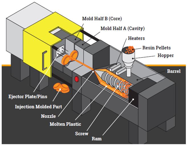
Our proprietary process engine creates ideal pressure, temperature and time cycle which is critical to creating high quality custom parts. Once the right environment inside the barrel is met, the ram moves forward driving the screw and channeling the molten plastic into the mold cavity through the nozzle. Once allowed to cool, the mold will open and the ejection plate engages, releasing the final part from the mold.
Injection Molding Basics
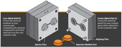
Injection Molds consist of two main components: the mold cavity and the mold core:
CORE (Mold Half B) – forms the main internal surfaces of your custom part CAVITY (Mold Half A) – forms the major external features
The cavity and core separate (Draw) along the parting line and, with the aid of ejector pins, releases the finished plastic part where the process can be repeated. Depending on your part design, the parting line can either fall on the top, bottom, stepped or angled to accommodate all irregular part features.
High quality, efficient tooling relies heavily on good part design as well as advanced skills in mold design and the manufacturing of the tool. An injection mold is a highly precision tool that must be rugged enough to withstand hundreds of thousands of high-pressure molding cycles. By optimizing your part design and focusing on consolidating many key features, you can reduce your overall investment costs significantly.
#1 – Text on Part
An added benefit to injection molded parts is the ease of incorporating logo’s, labels, instructions or diagrams right onto your custom parts; eliminating secondary costs often incurred with labeling and ensuring clear and precise identification of your custom plastic parts. Whatever the reason, incorporating text onto your plastic parts requires careful consideration and close attention to the details.

Text is often easier to incorporate if it is raised rather than recessed into your part design. Use clear bold letters typically 20 or higher point size for readability and ease of milling. A standard height for raised lettering is just 0.02 inches so do not feel you have to raise your lettering to help it stand out. Keep your font selection simple and try to avoid serif fonts. Serif fonts tend to incorporate curls or squiggle to the ends of the letters making them difficult to mill.
#2 – Hinges and Snaps
Thorough part design can often help reduce expenses when you face the need for fastening your plastic parts or require additional hardware installation such as hinges or fastening mechanisms. Hinges and snap-fit joints can be incorporated into your plastic parts and reduce or eliminate the need for traditional fasteners such as screws, nuts, washers and spacers.
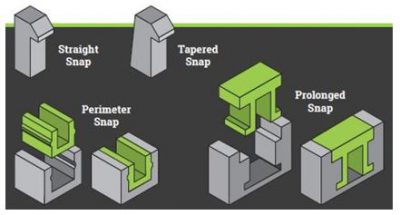
A part designed with molded-in hinges can replace metal ones while still performing the same function and reducing your products overall cost. When you reduce required hardware, you can lessen the material and assembly cost while also simplifying your design.
Snap joints should be considered during the development of your custom plastic components that need to be secured to other components. Versatile and cost effective, snap joints and hinges often reduce the cost of secondary hardware expenses and the labor of final assembly.
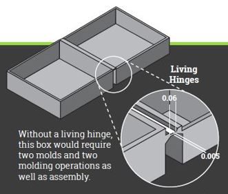
Polypropylene is the ideal plastic material for integral, injection molded hinges. Using a hinge to connect the box and cover, allows both parts to be produced in one molding operation. This reduces cost while enhancing functionality. The hinge must be .060 inch in width and at least .005 inch-thick to avoid a sharp bending of the hinge.
#3 – Threads
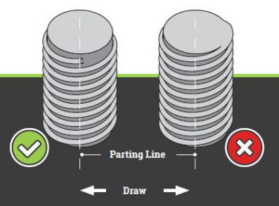
The molding process can incorporate threads right into your custom parts. This eliminates secondary thread cutting that can add unneeded costs to your final part. However, keep in mind thread locations can play a significant role in reducing your total tooling cost.
Placing external threads on the parting line is the most cost effective and easily implemented but can also add the potential for flash or mismatched threads. When threads are not centered on the parting line, side-actions or slides are required to produce the threads and can potentially add to your molding costs.
Stop threads short of the end to avoid making thin, feathered threads that can easily cross-thread. Limit thread pitch to no more than 32 threads per inch for ease of molding and protection from cross threading.
#4 – Insert Molding
Insert molding is the process of injection molding molten thermoplastic around pieces placed in the injection molding cavity resulting in a strong bond between integral pieces of your final part. Inserts are offered in a wide variety of materials including plastic, metals, ceramic or any other material that can withstand the pressures and temperatures of the injection mold process. There are many uses for plastic injection insert molding. Placing threads or securing wire connectors, knobs, controls, warnings, labels and electronic devices.

Insert molding is an effective and cost-efficient solution for reducing overall cost, by incorporating parts into the molding process which would otherwise require secondary assembly or installation. Accurate mold design and construction is essential to insert molding to not only maintain part tolerances but also assure the tooling reliability.
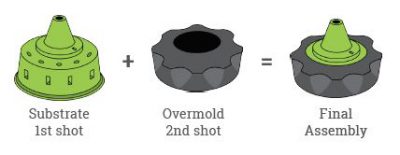
#5 – Overmolding
Overmolding plastic parts can help in wide range of functional and structural uses. Utilizing two separate injection molds, materials can be bonded together through the injection molding process to enhance the cosmetic look and/or functionality of your finished plastic part.
A wide range of materials are capable of being overmolded, including both hard and soft plastic resins. When you choose to overmold your parts most often you can reduce your overall investment by reducing added assembly processes and extra material to manufacture your custom parts.
Reasons to add overmolding into your design include: provide a soft grip surface, add flexibility to rigid part areas, eliminate assembly, and capture one part inside of another without having to use fasteners or adhesives.
Careful consideration and planning must be completed ideally from the concept phase and into prototyping. Part design, mold design and material selection are important when you plan to overmold your custom plastic components. It’s good practice to design features like holes and slots into your overmolded parts to help them interlock not only chemically but physically as well.
#6 – Surface Finishes
Quickparts offers a wide range of materials with multiple surface finish options. Most resins are available in many colors and we are also capable of creating custom colors to match your requirements. If you are working on a project that may require painting as a final process, consider utilizing molded-in color which can often be achieved for a much lower price than traditional painting labor and material costs.
If you must paint your plastic parts, select a resin that paints easily and preferably one that does not require surface etching and/or primer. Quickparts offers a variety of surface finishes to add function as well as cosmetics to your finished plastic injection molded parts. Available surface finishes include:
- B3 320 Paper Finish (Standard)
- B2 400 Paper (Smooth)
- A3 Polish (High Gloss Mirror Finish)
- A2 Optical Polish (Gloss Finish)
- MT- 11010 Bead Blast (Textured)
- MT- 11020 Bead Blast (More Textured)
Conclusion
Adhere to best practices in designing your part for the plastic injection molding process. Consider the following “checklist” as a baseline to meeting your part expectations.
Wall Thickness
• Maintain uniform Wall Thickness throughout
• Utilize Ribs to reinforce walls without adding to thickness
• A 10% increase in thickness = 33% increase in stiffness
• Core out unneeded thickness and wall stock
Draft
• Maintain a minimum of 0.5° draft angle on all features perpendicular to the parting line. 1° – 2° is ideal.
Tight Tolerances
• Utilize low-shrinkage materials for parts with tight tolerances
Ribs & Bosses
• Design ribs and bosses to approximately 60% of the joining wall thickness for minimum risk for sink marks.
Undercuts
• Undercuts will add cost to the mold. Minimize them when you can. Otherwise, there are no limits.
Corners and Transitions
• Use gradual transitions if wall thickness must change.
• Corners: R1 + T = R2
Access the full version of the Smart Guide to Designing for Manufacturability.
Interested in obtaining more advice? Reach a Technical Engineer at contact@quickparts.com